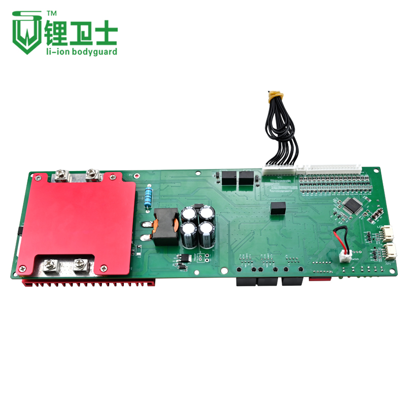
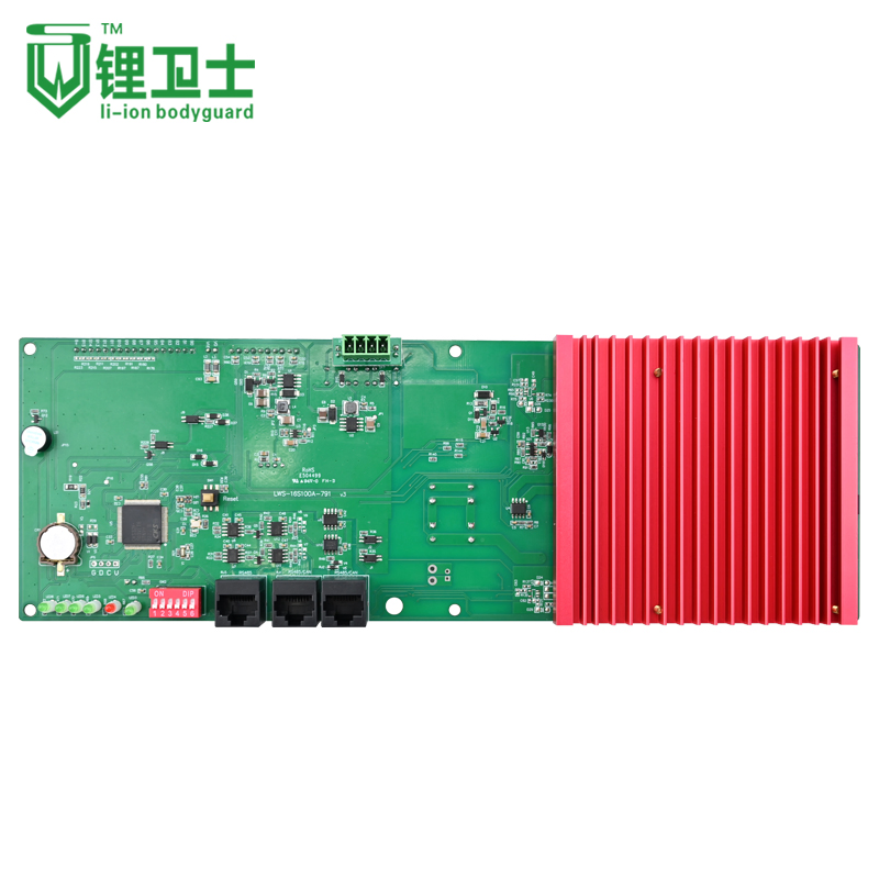
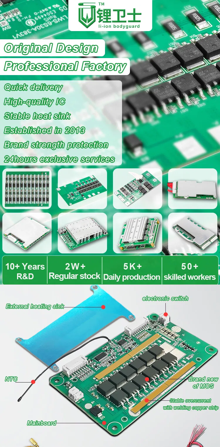
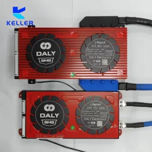
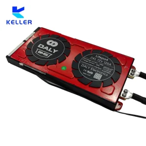
The 16S100A-791 battery management system is designed for battery packs with 5-16 series (5S-16S) of monomer voltage ranging from 2V to 5V. It offers comprehensive protection and recovery functions for the battery pack, including over-voltage, under-voltage, over-current, high temperature, low temperature, and short circuit protection. Moreover, it accurately measures the state of charge (SOC) during both charging and discharging processes and provides statistics for the state of health (SOH) of the battery.
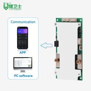
The battery management system incorporates various sleep and wake-up methods to optimize energy efficiency. Data communication with the host is facilitated through RS485, enabling easy access to parameter configuration and real-time data monitoring via the host computer software.
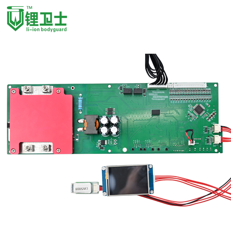
Accessories & Customization Info
Electric Switch, Temperature Switch, Passive Balance, Active Balance, 5V output, NTC, bluetooth UART/BT/RS485/CAN communication/LCD display etc. All items can be customized to your requirements. If no special requests are made after placing an order, production will follow standard detailed page specifications.
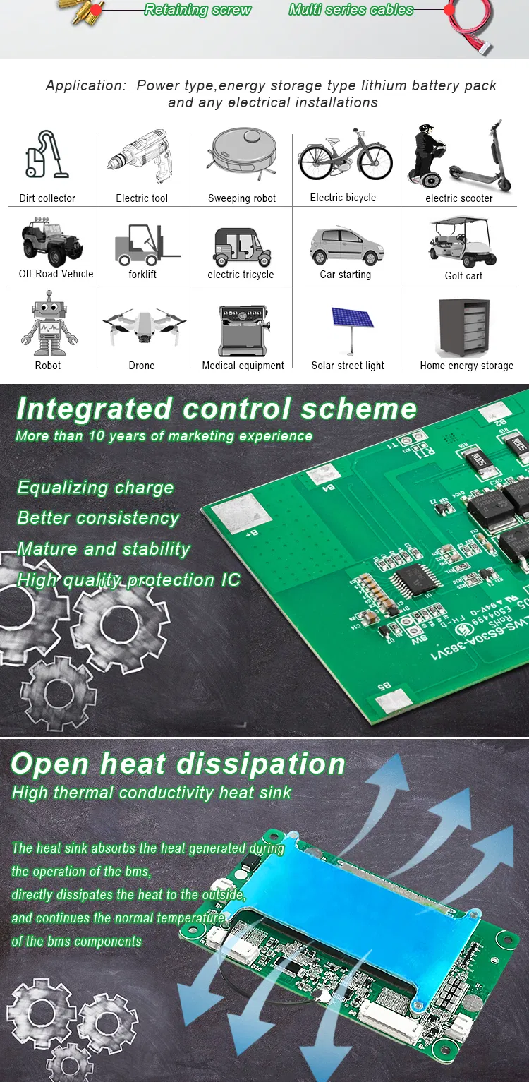
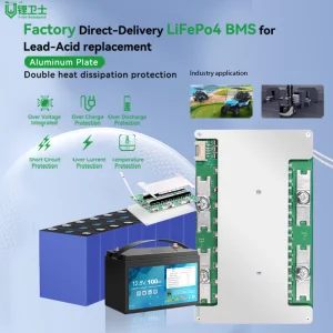
The 16S-100A-791 battery management system is versatile, serving as backup batteries for communication base stations and optimizing household energy storage. It offers comprehensive protection, precise SOC measurement, and passive balancing, ensuring efficient energy storage and improved system performance.
Li-ion Product Specifications
Product Parameters
15A
25A
30A
40A
100A
200A
Supplement
Current
Max continuous charging current
15A
25A
30A
40A
100A
200A
Provide us your rated voltage, current, or application details, and we will recommend the most suitable configuration.
Max continuous discharging current
15A
25A
30A
40A
100A
200A
Over Current Protection
Over current detection current
80±20A
120±20A
120±20A
120±20A
300±50A
600±100A
Resistance
Protection circuitry (MOSFET)
≤20mΩ
≤20mΩ
≤20mΩ
≤20mΩ
≤20mΩ
≤20mΩ
Consumption
Current consumption
≤20μA
≤20μA
≤25μA
≤25μA
≤20μA
≤50μA
Voltage
Charging voltage
DC: 54.6V CC/CV 4.2V/cell
Balance voltage for single cell
4.25±0.025V
Balance
Balance current for single cell
42±5mA
Over Charge Protection
Detection voltage (single cell)
4.25±0.025V
Detection delay time
500mS-1500mS
Customizable
Release voltage (single cell)
4.15±0.05V
Customizable
Over Discharge Protection
Detection voltage (single cell)
2.75±0.08V
Customizable
Detection delay time
500mS-1500mS
Customizable
Release voltage (single cell)
3.0±1.0V
Customizable
Over Current
Detection voltage
0.1±0.025V
Customizable
Release condition
Cut load, Automatic recovery
-
Short Protection
Detection condition
Exterior short circuit
-
Detection delay time
200-500uS
Customizable
Release condition
Cut load, Automatic recovery
-
Temperature
Operating Temperature Range
-20~+65ºC
Customizable
Storage Temperature Range
-20~+85ºC
Customizable
LiFePO4 Product Specifications
Product Parameters
15A
25A
30A
40A
100A
200A
Supplement
Current
Max continuous charging current
15A
25A
30A
40A
100A
200A
Provide us your rated voltage, current, or application details, and we will recommend the most suitable configuration.
Max continuous discharging current
15A
25A
30A
40A
100A
200A
Over Current Protection
Over current detection current
80±20A
120±20A
120±20A
120±20A
300±50A
600±100A
Resistance
Protection circuitry (MOSFET)
≤20mΩ
≤20mΩ
≤20mΩ
≤20mΩ
≤20mΩ
≤20mΩ
Consumption
Current consumption
≤20μA
≤20μA
≤25μA
≤25μA
≤20μA
≤50μA
Voltage
Charging voltage
DC: 46.8V CC/CV 3.6V/cell
Balance voltage for single cell
3.60±0.025V
Balance
Balance current for single cell
36±5mA
Over Charge Protection
Detection voltage (single cell)
3.90±0.025V
Detection delay time
0.5S-2S
Customizable
Release voltage (single cell)
3.80±0.025V
Customizable
Over Discharge Protection
Detection voltage (single cell)
2.00±0.05V
Customizable
Detection delay time
10mS-200mS
Customizable
Release voltage (single cell)
2.50±0.05V
Customizable
Over Current
Detection voltage
0.10±0.015V
Customizable
Release condition
Cut load, Automatic recovery
-
Short Protection
Detection condition
Exterior short circuit
-
Detection delay time
200-500uS
Customizable
Release condition
Cut load, Automatic recovery
-
Temperature
Operating Temperature Range
-40~+65ºC
Customizable
Storage Temperature Range
-40~+125ºC
Customizable
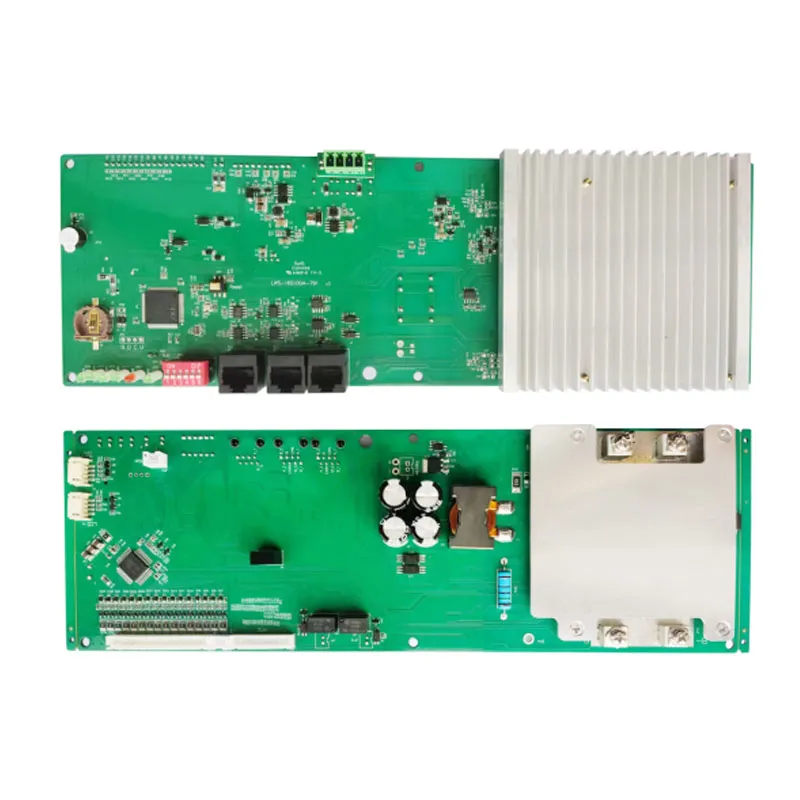
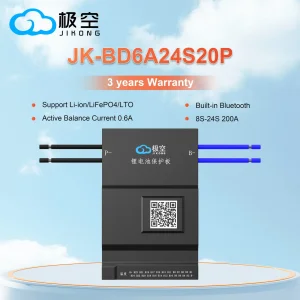
This premium 4~16S 100A protection circuit module BMS supports CAN, RS485, and Bluetooth protocols for both Li-ion and LiFePO4 battery applications. These configurations are customizable, highly durable, and CE certified to align with specialized energy storage requirements.
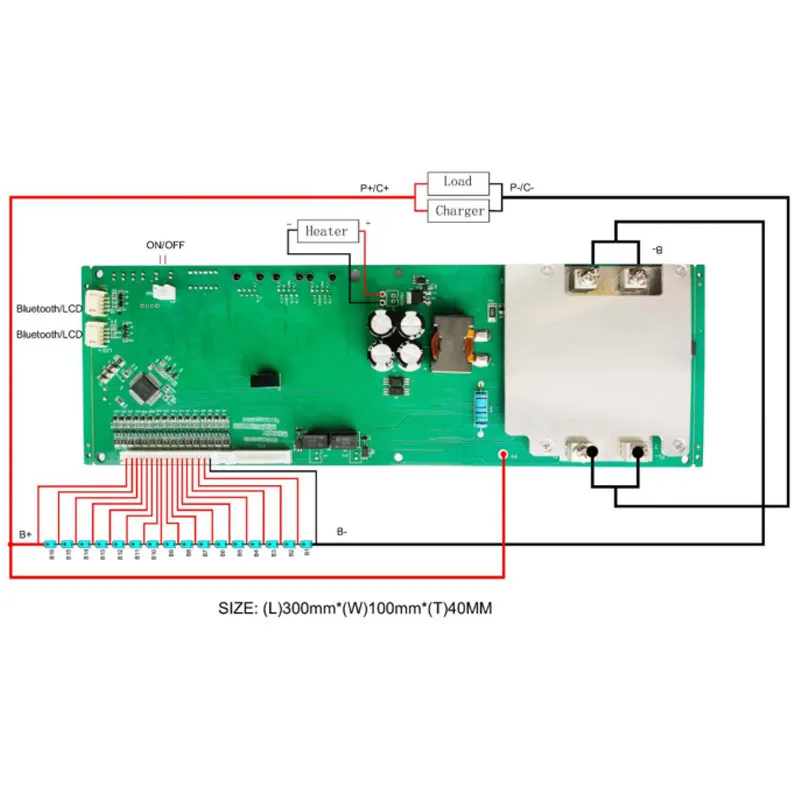
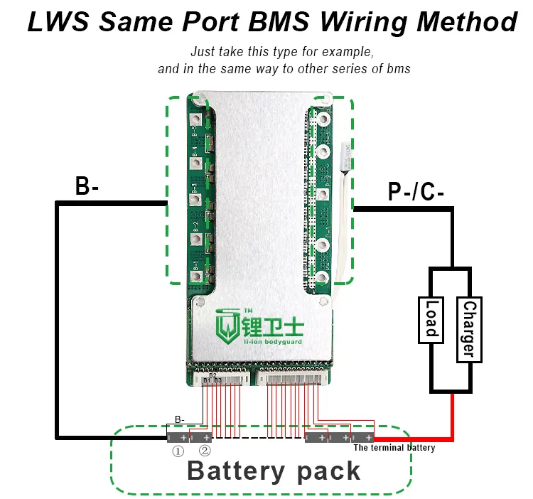
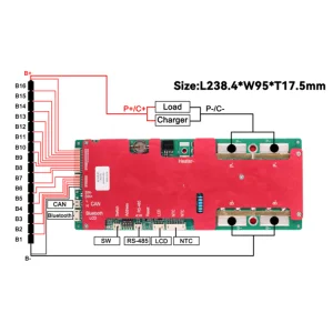
Wiring Connection Steps
First Step:
Connect the B- to the battery negative terminal (the B- needs to be welded first). Then connect the cables (ensure cables are detached from the BMS before wiring).
Second Step:
Start wiring from B-. Connect B- to the battery's total negative terminal (battery #1 negative). The sideline B1 connects to the positive of battery #1, B2 to the positive of battery #2, B3 to the positive of battery #3, and so forth.
Third Step:
After completing the cable wiring, test the voltage between adjacent lines. The voltage of Li-ion batteries should be less than 4V, and the voltage of LiFePO4 batteries should be less than 3.5V. Once verified, insert the line connector into the BMS.
Fourth Step:
Connect the negative terminal of the charger and load to P- / C-. The B- and P- / C- connections must use bold wires. Make sure the installation order is strictly followed.
Frequently Asked Questions
Q: How do I judge what material my battery is?
A: Please check the battery body. If the normal voltage of your battery is 3.2V, the battery is LiFePO4. If the normal voltage is 3.6V or 3.7V, it is a Li-ion or Li-polymer battery. You can also consult the battery cell manufacturer.
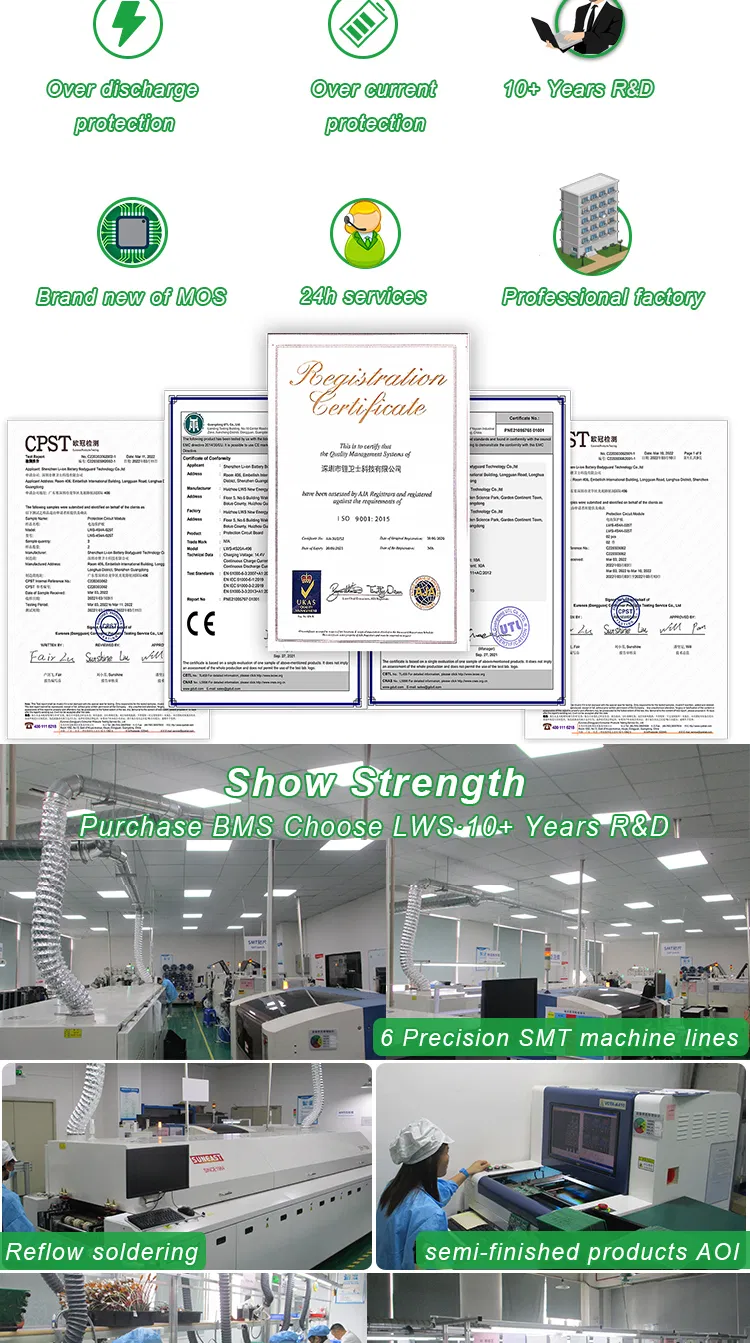
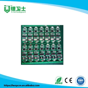
Q: How is the quality of these protection circuit boards guaranteed?
A: Quality is managed via a pre-production sample verified prior to mass production, followed by a final 100% inspection and testing process before shipment.
Q: What products are available for purchase in this category?
A: You can purchase Battery Pack BMS, LiFePO4 / Lithium Ion PCM, Protection Circuit Boards, Printed Circuit Boards, and LiFePO4 / Lithium Ion Battery Packs.
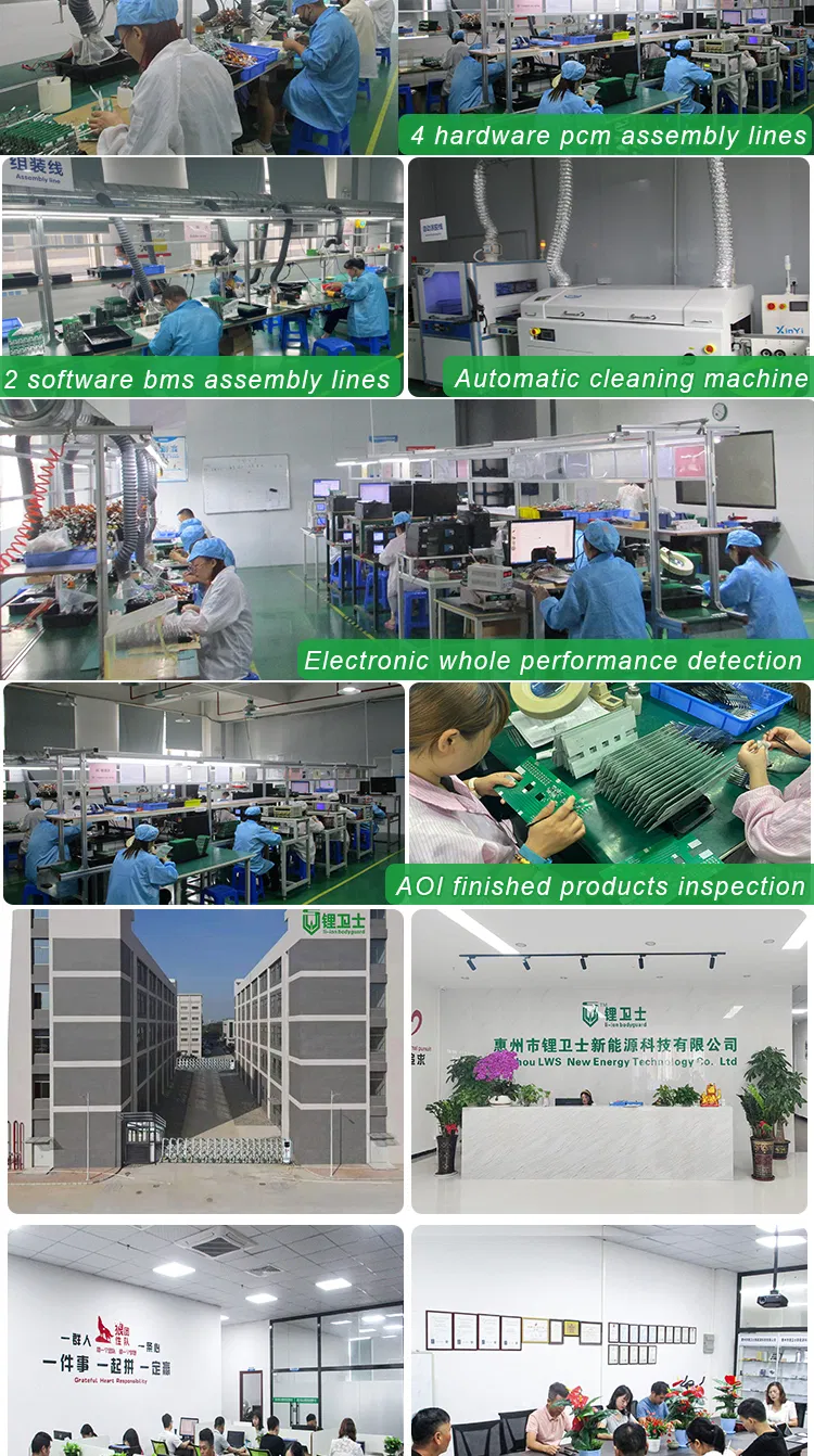
Q: Why should these products be purchased over other supplier alternatives?
A: The manufacturing processes utilize advanced production machinery alongside a complete, scientific quality control system, emphasizing environmental standards and product durability.
Q: What delivery terms and payment services are provided?
A: Accepted delivery terms include FOB and EXW. Payments are accepted in USD and CNY via T/T, PayPal, Western Union, or Cash. Supported communication languages are English and Chinese.
Q: How can I request advice on selecting the right products?
A: Please specify your battery voltage, cell type, operational current, or device requirements, and we will assist you in selecting the ideal BMS configuration.